Recreating an aircraft that nobody alive has ever seen is not an easy task.
To do so without any of the documentary evidence is even more tricky. It is a mixture of research, calculation, interpolation, some clever geometry and a certain amount of guesswork. as aircraft contain a lot of parts. To make it easier to think about they can be broken down into assemblies, sub-assemblies and components for ease of reference.
Most of the parts for the Panther are being made from scratch with others purchased and keeping track of all of the parts and assemblies is a bit of a job in itself. Not to mention ensuring that they all fit together as they are supposed to once the aircraft has been built is pretty fundamental to my work here.
To put the issue into context, the set of drawings that would have originally existed to build the Panther would quite likely have been about two to three inches thick – unfolded. This is a lot of information to manage. The way that companies used to achieve this task was through a drawing office. Very simply – the designer directed a draughtsman to produce a drawing of a aircraft, the drawing was checked and logged and issued to the shop floor, any issues or mistakes were reported back by the works foreman and the drawing would be modified and reissued and so on.
Control of drawings was essential for operations. People think of drawings as being a piece of paper with a picture on, but in fact the drawing is a highly sophisticated and highly detailed set of instructions that communicate the making of a highly complex object to a person. I like to think of drawings as being one of the most highly evolved communication tools that humans have ever really created. The world we live in has drawings at its foundation.
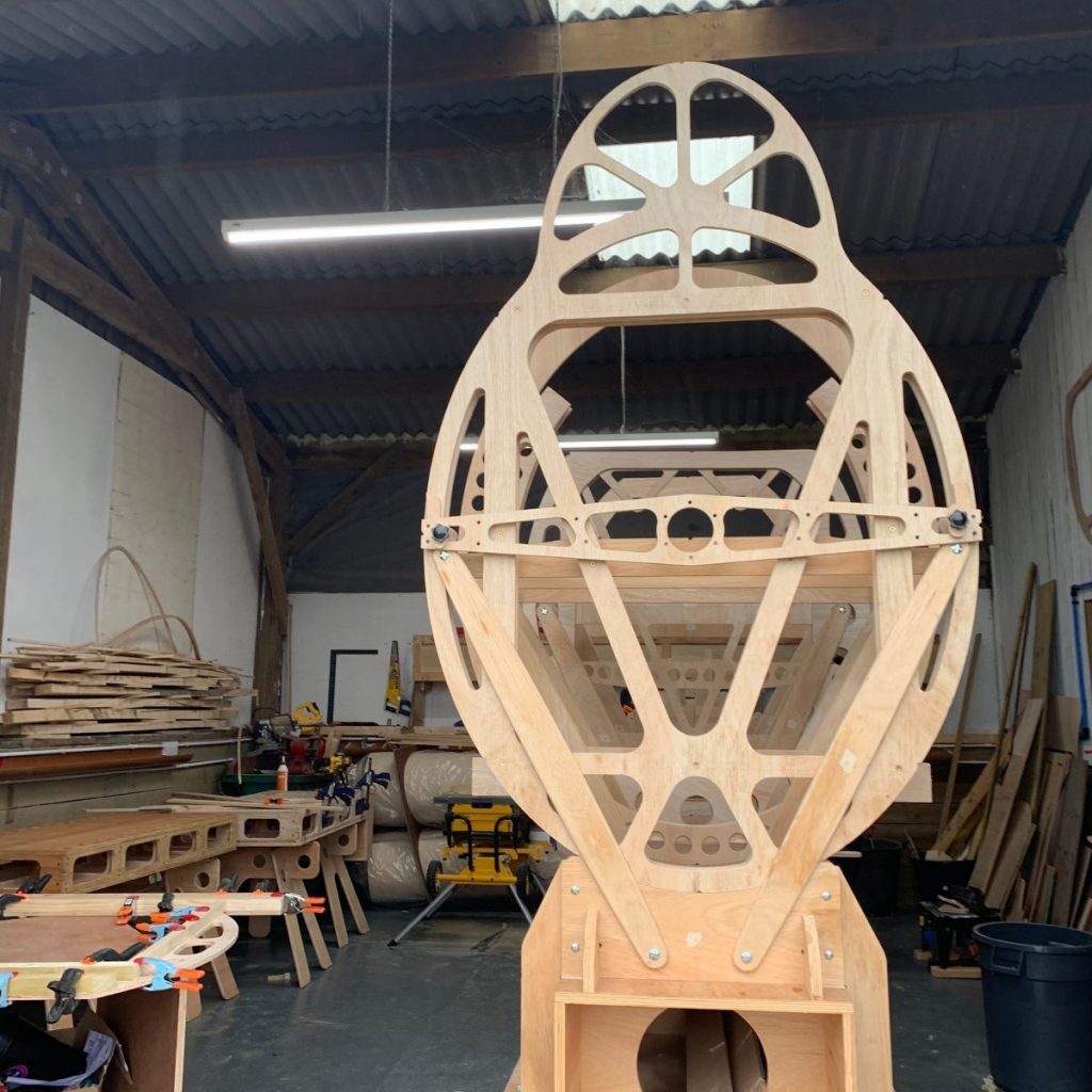
So, how do I get on with the quantity of drawings required? Quite simply, I don’t. If I can possibly help it I never create a single drawing. It’s time consuming and tedious. A drawing is by its nature a two dimensional thing – and two dimensional things don’t exist. There are two central tools that I use daily to create objects. Computer aided design (CAD) and Computer Numerical Cutting (CNC). The CAD package I use is a 3D modelling package in which I create a full sized virtual model of every part of the thing I am trying to build. If the parts fit on screen, they will also fit in real life, which is where the CNC comes in. People tend to think of CAD packages as being tools to create drawings. Whilst it is is true that they can create drawings, this is only really necessary as an export function to other people to make things. A communication document at heart. The information that can be extracted from a 3D model is far more detailed, accurate and interesting.
I communicate my design information to as few people as possible to avoid communication problems. The one person who plays a key role in the process however is the man who does the CNC cutting. I send him absolute cutting files of the things/parts I want made with instructions as to what it should be made from, and the parts come back to me exactly as I want them.
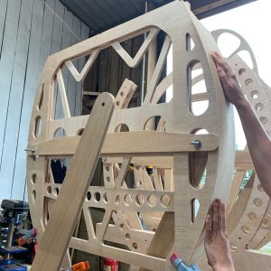
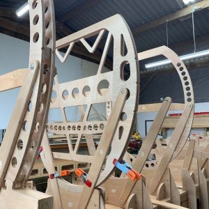
I have to ensure that I have thought far enough ahead to provide me with any position marks, inscription or tolerance references and allowed for any discrepancies in the material (such as thickness). Normally the things I have made are profiles, but complex three dimensional shapes are also pretty easy to generate. It just comes down to thinking and planning ahead. The fact that everything works from one, constantly evolving master model means that things do fit, there is very little rework, and everything goes fairly smoothly. Of course, one does make mistakes from time to time. The power of modern computing is vast, but to err is human.
(All Images © Parnall Panther Ltd)